
I understand that this location varied some from one LT-1 to another. Anyone know what kind of tool/template they used? Just curious, since about 1 in 12 cars was LT-1.
-
-
Re: How did they drill/locate holes for TI amp in fendewell?
It could not have been much of a template because I have seen them anywhere from rubbing on the hood to so far outboard that the only way we could tell something was there was by braille. There must have been some kind of template to locate the three holes to each other, but beyond that I doubt there was anything. If there was, it was a major fail.Terry -
Re: How did they drill/locate holes for TI amp in fendewell?
When I installed the TI amp on my fender skirt there was 3 dimples in the molding for locating drilled holes. It was a perfect match for mounting the amp. The dimples were located on the forward side of the fender skirt. The dimples were very minute and difficult to see.Comment
-
Re: How did they drill/locate holes for TI amp in fendewell?
Terry------
That's exactly how it was done. While not shown in the 1971 AIM, the use of the dimples to establish the correct location for drilling the mounting holes for the TI amplifier is shown in earlier C3 AIM's. The exact same procedure was used for 1971, the last year that TI was available in a Corvette.In Appreciation of John HinckleyComment
-
Re: How did they drill/locate holes for TI amp in fendewell?
They certainly didn't pay any attention to the dimples---did they use some kind of three-headed drill to ensure spacing? A cant-miss template that ensured hole spacing but not location?????Comment
-
Re: How did they drill/locate holes for TI amp in fendewell?
I've often wondered this. I know they were supposed to use the dimples to drill
but how did they get the drill in there? A template on the back side would be easier.
Cheers, Graeme.Comment
-
Re: How did they drill/locate holes for TI amp in fendewell?
Graeme -
Most of the assembly plant-drilled holes in the inner fenders were done before the inner fender was loaded into the front clip bonding fixture; that's also when the rubber splash shields were stapled to the inner fenders, and any brackets/reinforcements were riveted to the inner fender.Comment
-
Re: How did they drill/locate holes for TI amp in fendewell?
John--
Did they drill the holes indidually, or with a specifically designed and special-built tool?Comment
-
Re: How did they drill/locate holes for TI amp in fendewell?
John------
That's how I would expect it, too. If dimples were present I can't imagine there would be any easier way to drill the holes, including a template.
As far as a "3 headed drill" being used that would seem very unlikely to me, especially to facilitate the installation of an option that was specified only on a minority of cars built.
However, the above is applicable to 1968-71 Corvettes which is the original subject of this thread. I don't know if dimples were present on 64-67 panels. If not, I would expect that some sort of template would have been used.In Appreciation of John HinckleyComment
-
Re: How did they drill/locate holes for TI amp in fendewell?
If I remember right using the dimples on a 69 I had would have caused the TI to be mounted right where a reinforcing bracket was located. The reinforcing bracket was added sometime during the 68-69 era.Comment
-
Re: How did they drill/locate holes for TI amp in fendewell?
All------
Can anyone post a photo of the REAR of the panel to which the TI amplifier is attached on an original TI 1969-71 Corvette and showing at least the rear of the fasteners securing the amp to the panel?In Appreciation of John HinckleyComment
-
Re: How did they drill/locate holes for TI amp in fendewell?
Joe ,I would like to see a photo too. I'm sure a lot weren't drilled before assembly and maybe some drilled that weren't supposed to be.
Cheers Graeme.Comment
-
Re: How did they drill/locate holes for TI amp in fendewell?
Is this what you mean?
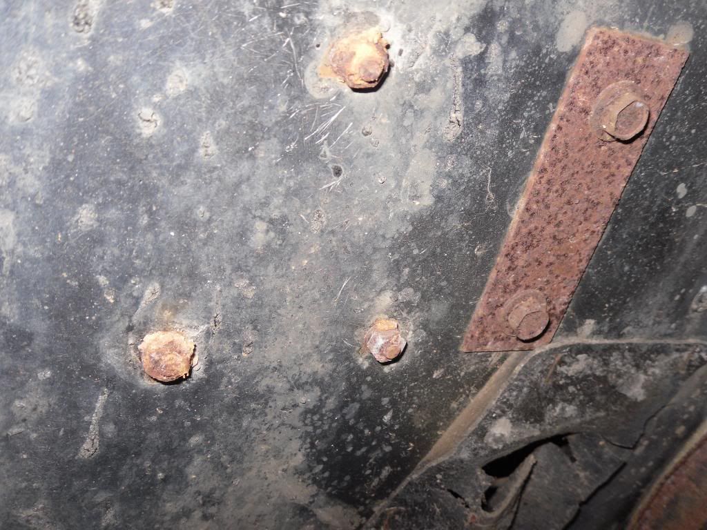
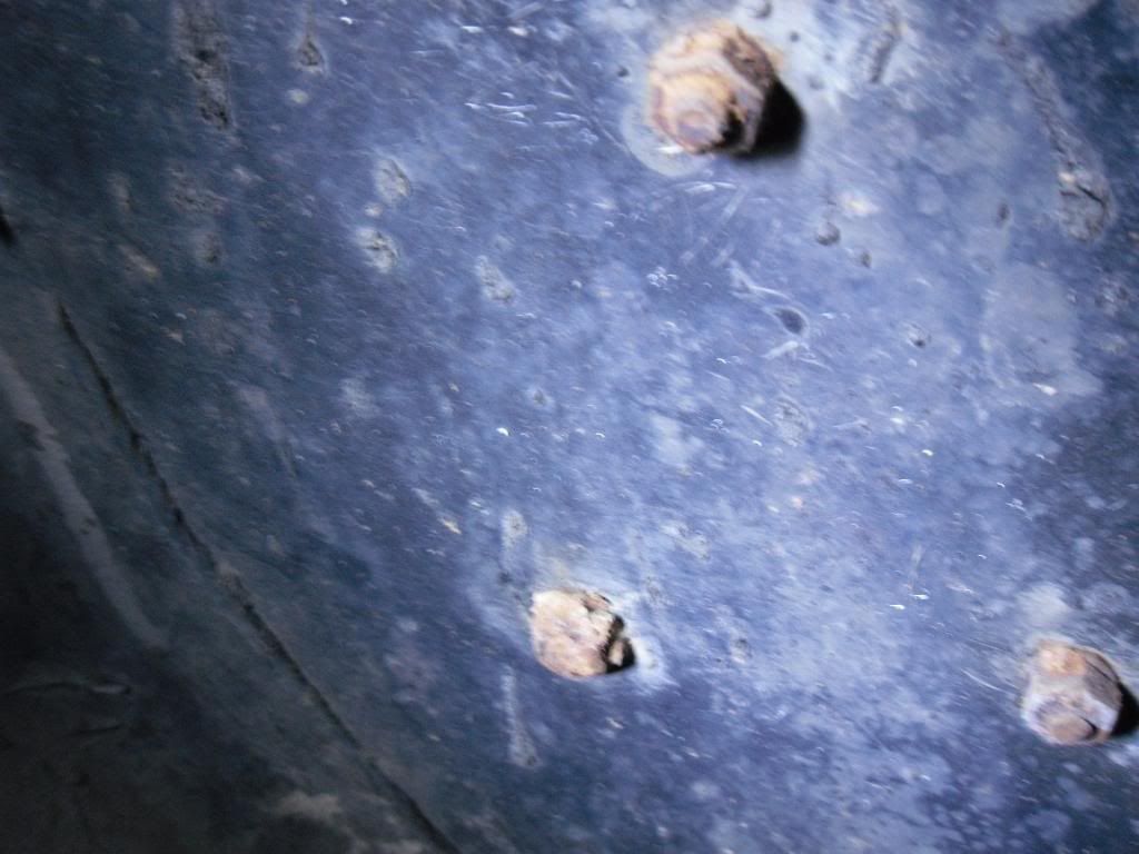
Comment
-
Re: How did they drill/locate holes for TI amp in fendewell?
Thanks Keith, that's exactly what we mean.
My L71 was in that position but I was told it should go on the other side of the reinforcing bracket.
Cheers, Graeme.Comment


Comment